Custom Sheet Metal Fabrication | Drawing to Assembly
Custom sheet metal fabrication for industrial OEMs: laser cutting, CNC bending, welding, PEM hardware, assembly, and partner finishing. Prototypes to repeat production.
View details →We run fiber laser cutting, CNC punching, precision bending, welding, hardware insertion, in-house surface prep, partner finishing, and assembly for industrial OEM parts. Our team gives DFM feedback before metal is cut so you can plan tolerances, finish sequence, and lead time with fewer surprises.
Equipment snapshot
5 fiber lasers (to 2000 × 4000 mm), 7 CNC press brakes (to 230T / 3000 mm), CNC punching, and multi-process welding in our 3,500 m² Dongguan facility.
Typical tolerances
Laser ±0.10 mm; bending ±0.20–0.30 mm; holes ±0.10–0.20 mm—always confirmed against your drawing, material, and geometry.
DFM / RFQ cues
Share STEP/DXF/PDF, bend notes, PEM callouts, weld symbols, finish specs, and critical faces so we can flag risk before nesting.
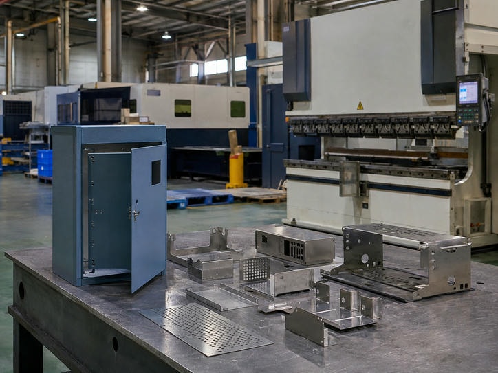
Most OEM parts we build are not laser-only blanks. A typical enclosure, chassis, or bracket stack moves through flat-pattern review, cutting or punching, CNC bending, hardware insertion, welding or grinding where required, then in-house prep and partner finishing. We keep that chain under one project owner so you are not coordinating three shops for one assembly.
Fiber laser profiles sheet to 2000 × 4000 mm. Typical capacity: stainless to 20 mm, carbon steel to 25 mm, aluminum to 16 mm. CNC punching is used when dense hole patterns, louvers, or formed features are more efficient than laser-only nesting. We review kerf, micro-joints, grain direction, and nest efficiency against cosmetic faces you mark on the drawing.
If your design mixes thick structural panels with thin covers, we split process notes by thickness so bend and weld assumptions stay realistic. Edge quality expectations (as-cut, deburred, or brushed) should be stated in the RFQ—especially for visible faces and gasket lands.
CNC press brakes to 230T / 3000 mm handle enclosure boxes, U-channels, brackets, and frames. We review bend sequence, reliefs, minimum flange length, and punch/die selection before first article. PEM nuts/standoffs, riveting, and M2–M12 tapping are inserted so panels arrive ready for line assembly.
TIG, MIG/MAG, laser, and spot welding cover structural and cosmetic weldments. Call out grind/brush zones and distortion-sensitive faces early; we will propose stitch vs continuous welds or fixture notes when the drawing leaves that open.
The ranges below are planning values our team uses when reviewing RFQs. Final capability always depends on material grade, thickness, feature density, and your GD&T. Call out datum schemes and cosmetic faces so we can confirm process capability before we commit lead time.
Email-only RFQs work best when the package answers process questions up front. Incomplete drawings force assumptions on bend reliefs, hardware, and finish that later become change orders.
Our ISO 9001:2015 quality flow covers IQC, FAI, IPQC, FQC, and OQC. Inspection resources include CMM, 2.5D vision, height gauges, and standard metrology when your drawing or PO requires documented checks. Available paperwork includes first-article inspection, dimensional reports, material certificates, RoHS/REACH statements, and coating reports from finishing partners when applicable.
Typical lead times (confirm against scope and finish queue): prototypes 3–12 working days; small batches 10–15 days; regular production 15–25 days. MOQ of one piece is available for fit and process checks. Child process pages below detail laser cutting, punching, bending, welding, hardware, finishing, and assembly—use them for process-specific notes, then send the drawing package for a firm review.
Custom sheet metal fabrication for industrial OEMs: laser cutting, CNC bending, welding, PEM hardware, assembly, and partner finishing. Prototypes to repeat production.
View details →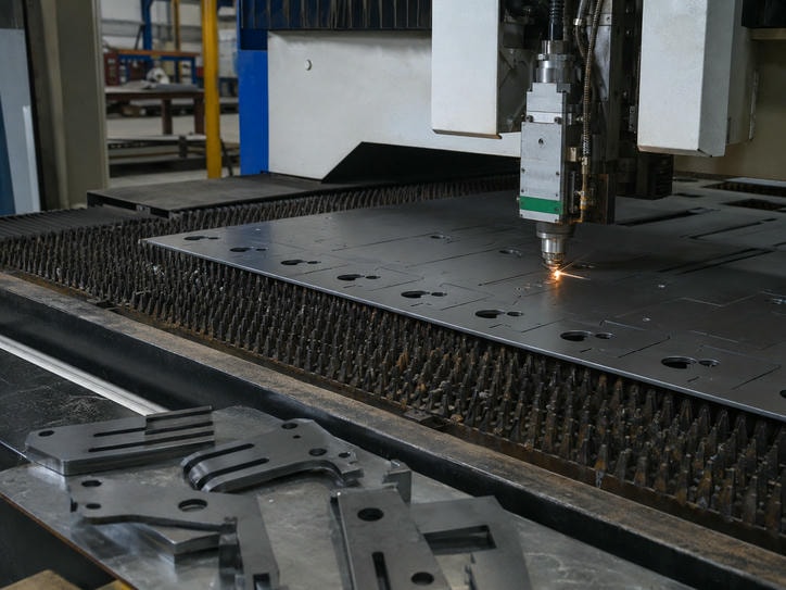
Fiber laser cutting to 2000 × 4000 mm for OEM sheet metal. Typical capacity: stainless to 20 mm, carbon steel to 25 mm, aluminum to 16 mm. Drawing-based RFQs.
View details →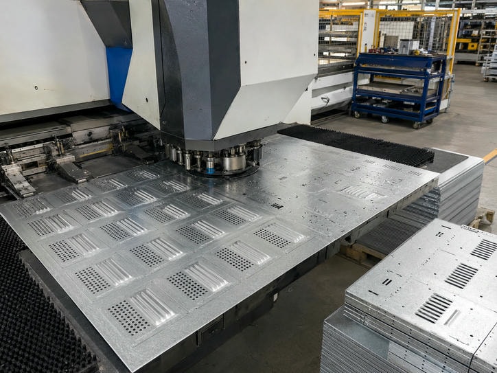
CNC punching for repeatable holes, louvers, and formed features on industrial sheet metal panels and enclosures. Efficient nesting for OEM production runs.
View details →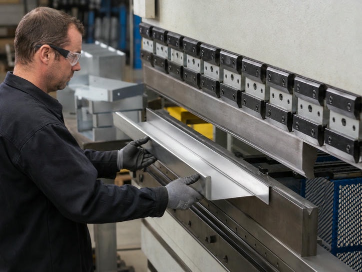
CNC press-brake bending to 230T / 3000 mm with bend-sequence review. Typical bend tolerance ±0.20–0.30 mm for enclosures, brackets, and frames.
View details →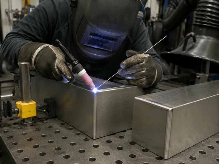
TIG, MIG/MAG, laser, and spot welding with grind and brush cleanup for structural and cosmetic sheet metal weldments. FAI support available on request.
View details →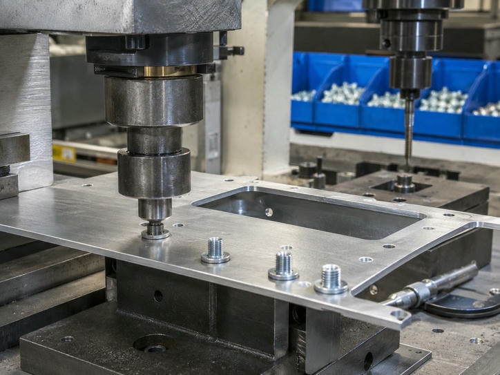
Self-clinching PEM hardware, riveting, and M2–M12 tapping for panels, chassis, and enclosures that need production-ready fastener interfaces.
View details →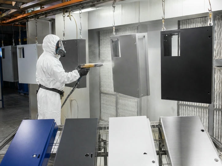
In-house deburr, grind, and brush. Powder coating, anodizing, plating, passivation, and marking coordinated through qualified finishing partners.
View details →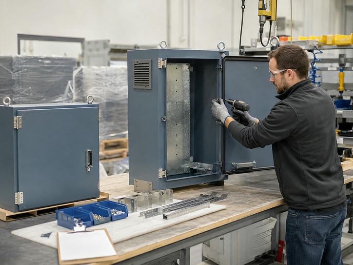
Fabricated-part and hardware assembly support so multi-piece sheet metal builds ship with fewer supplier handoffs. Prototype through repeat production.
View details →